Mark Pawley1, Jonathan Irvine1, Angela Melville2, Carmen Krapf1, Stephan Thiel1, Ignacio González-Álvarez3, 4, Ulrich Kelka3 and Cericia Martinez3
1 Geological Survey of South Australia, Department for Energy and Mining
2 College of Business, Government and Law, Flinders University
3 Discovery Program, CSIRO Mineral Resources
4 Centre for Exploration Targeting, University of Western Australia
Download this article as a PDF (6.4 MB); cite as MESA Journal 95, pages 30–40
Published October 2021
Contents
Introduction
Method of automatically generating lineaments
Automatically generated lineaments and the Gairdner Dolerite dyke swarm
Implications for the Gairdner Dolerite dyke swarm and the Gawler Craton
Implications for controls on mineralisation
Implications for computer-generated lineaments
Acknowledgements
References
Introduction
In extensively covered regions, such as the Gawler Craton, understanding crustal architecture and the relation between geological structures, lithologies and mineral systems is dependent upon remote-sensed data, such as aeromagnetics. However, the large-scale interpretation of geophysical datasets can be time consuming and subjective. In 2019–20 an innovative collaborative project between the Geological Survey of South Australia and CSIRO, aiming to link basement lineaments with surface lineaments (González-Álvarez et al. 2020), resulted in the development of an automated lineament extraction and analysis workflow by Kelka and Martínez (2019). This methodology was applied successfully to an area in the central Gawler Craton (González-Álvarez et al. 2020; Kelka and Martínez 2019). This process allows the automatic generation of lineaments across large datasets in a time and cost-efficient way. Importantly, the generated lineament dataset includes derivative data, such as line length, orientation and line density, which can be used to analyse the data more objectively and statistically compare populations.
Despite the potential value of automated lineament generation, there has been little work comparing the product derived from this innovative process against manual observations. An analysis of the Gairdner Dolerite dykes provides an excellent craton-scale case study to test the automated extraction and analysis process of Kelka and Martínez (2019). The c. 825 Ma Gairdner Dolerite dykes are highly magnetic and form laterally continuous features (Goode 1970; Wingate et al. 1998), which are largely concentrated within a northwest-trending, 150 km wide swarm that can be traced across the Gawler Craton for almost 750 km. The outlines of the dykes have previously been interpreted (South Australian Resources Information Gateway, SARIG: ‘All Map Layers’, ‘Gairdner Dolerite’), but little attention had been paid to the detailed orientation of the dykes during solid geology interpretation. Instead, most regional interpretations have focused on trying to determine the trends within the host basement rocks.
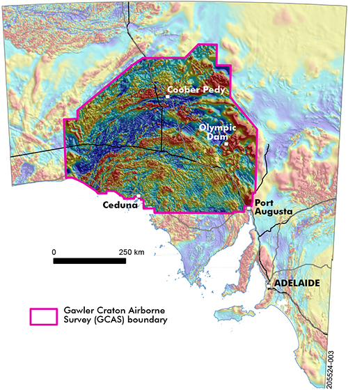
Figure 1 Location map showing the Gawler Craton Airborne Survey TMI RTP data in full colour over semi-transparent state TMI RTP image.
This paper has 3 aims. First, it tests the usefulness of the products derived from automated lineament generation against those derived from manual observations in relation to the Gairdner Dolerite dykes that are prominent on aeromagnetic datasets of the Gawler Craton. The new Gawler Craton Airborne Survey (GCAS) dataset represents a significant improvement on previously available aeromagnetic data (Fig 1; Katona et al. 2019) and represents an excellent dataset to test the new interpretation workflow developed by Kelka and Martínez (2019). The results from the GCAS dataset are compared with those generated from statewide total magnetic intensity (TMI) data and the manually interpreted dykes.
The second aim is to examine the geological implications that are revealed by the lineaments in the 3 datasets. The lineaments highlight a prominent change in dyke orientation across an east-northeast-trending corridor in the central and eastern parts of the craton, which has implications for the interpreted architecture of the Gawler Craton and the crustal-scale expression of structures. The derivative data associated with the automatic generated lineaments can be analysed to determine whether the change in orientation is significant.
The third aim is to evaluate some of the reasons for differences between the computer-generated ‘objective’, and manually interpreted ‘subjective’ lines corresponding to the dykes. This work highlights the increasing usefulness of automated data extraction and analysis for large regional datasets. In particular, the process has potential for revealing patterns in geophysical datasets and highlighting areas of complexity that warrant further investigation.
Method of automatically generating lineaments
The GCAS provided new data products including magnetic, radiometric and laser digital elevation model across the central and northern parts of the Gawler Craton (Fig 1). GCAS was flown at 200 m line spacing, with 60 m terrain clearance (Foss et al. 2019; Katona et al. 2019). Additional metadata and descriptions of the 16 GCAS region datasets are available on SARIG (‘All Map Layers’, ‘Gawler Craton Airborne Survey’). The TMI reduced to pole (TMI RTP) data was used for automated lineament mapping in this study.
Automatic lineament delineation with PCI Geomatica
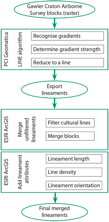
Figure 2 Flow chart showing the procedure for generating and determining the values of the lineaments.
The automatically extracted lineaments were generated by the ‘Lineament Extraction’ (LINE) algorithm within PCI Geomatica software using 40 m resolution magnetic raster images for each of the individual GCAS regions. A trial licence for Geomatica was obtained to perform this step. The workflow for extracting and determining values for the lineaments is shown in Figure 2.
The LINE algorithm allows a series of parameters to be changed, which affect the results and detail of the generated lineaments (Table 1). The input parameters are more fully documented in the software user’s manual (PCI Geomatics 2019) and a recent CSIRO report (Kelka and Martínez 2019) that applied the technique to the GCAS Region 9A area. The parameters include:
- Filter radius – specifies the pixel distance of edge detection filtering. Smaller values will detect more detail in linear edges, whereas larger values can be used to minimise the detection of noise. The input value can range from 0 to 8,192 pixels.
- Edge gradient threshold – specifies the minimum threshold change to define an edge pixel. The values can range from 0 to 255.
- Curve length threshold – used for mapping curved features as valid lineaments. The value specifies the minimum threshold of curvature (in pixel distance) that can be considered part of the same curve or lineament. The input value can range from 0 to 8,192 pixels.
- Line fitting error threshold – specifies the maximum error (in pixel distance) allowed in fitting a vector GIS arc to pixels defining a curved feature. Lower values yield better fits using shorter lines with a higher number of arc segments, whereas higher values yield coarser fits using longer lines and arcs with fewer segments. The input value can range from 0 to 8,192 pixels.
- Angular difference threshold – specifies the maximum angle (in degrees) between 2 neighbouring arc segments, below which they can be linked into a single vector arc. The values can range from 0 to 90°.
- Linking distance threshold – specifies the minimum distance (in pixels) between the end points of 2 arcs for them to be linked. The values range from 0 to 8,192 pixels.
The values for these parameters used in this study are the same as those used in the recent case study by Kelka and Martínez (2019). These values are shown in Table 1.
Table 1 Variable parameters in the LINE algorithm and the values used in lineament generation
| Input parameter | Value | Spatial value (m) |
| Filter radius | 20 pixels | 800 |
| Edge gradient threshold | 20 | — |
| Curve length threshold | 100 pixels | 4,000 |
| Line fitting error threshold | 100 pixels | 4,000 |
| Angular difference threshold | 15° | — |
| Linking distance threshold | 50 pixels | 2,000 |
The LINE algorithm was applied to the raster data in a 3-step execution process consisting of: (1) edge detection; (2) thresholding; and (3) feature extraction (Fig 2; PCI Geomatics 2019).
In the first stage, the Canny’s edge detection algorithm is applied to produce an edge strength image. The input image is filtered with a Gaussian function using the radius provided by the filter radius parameter. The gradient is then computed from the filtered image. Finally, pixels without the local maximum gradient are suppressed.
In the second stage, the edge strength image is calibrated as per the threshold to obtain a binary image. Each ON pixel of the binary image represents an edge element as defined by the edge gradient threshold parameter.
In the third stage, curves are extracted from the binary edge image. Consisting of several substeps, firstly a thinning algorithm is applied to the binary edge image to produce pixel-wide curves. Then, a sequence of pixels for each curve is extracted from the image. Any curve less than the curve length threshold value is discarded from any further processing. The extracted pixel curve is converted to a vector line by fitting line segments to it. The resulting polyline approximates the original pixel curve, where the maximum fitting error follows the line fitting error threshold value. Finally, the algorithm then links pairs of arcs that satisfy the following criteria:
- Two end segments of the 2 arcs face each other and have similar orientation (less than the specified angular difference threshold value).
- The 2 end segments are close to each other (less than the specified linking distance threshold value).
This process was applied to each of the GCAS regions using the parameters developed by Kelka and Martínez (2019) for their study of the GCAS Region 9A. These parameters may need to be reviewed once a single merged dataset containing all 16 individual regions is available. Within each GCAS region, lineaments have been extracted from the TMI RTP. The final seamless product was produced by first removing redundant lineaments from edges of each GCAS region. The append tool of ArcGIS software was then used to reassemble all lineaments along the boundaries of each region back into a GCAS-wide coverage.
It should be noted that linear features mapped by automated (or visual) interpretation of remote-sensing data may represent cultural features, such as roads or possibly water features, and may not represent a geologic feature. As such, automated-derived lineaments will require cross-comparison with other data sources, such as the manually derived interpretations, or follow up field investigations to avoid including lineaments that are not geological in origin.
Once the lineaments are generated, ArcGIS can be used to calculate values for various attributes. From the lineaments, a line density map can be generated to better visualise lineament density zones within the data, possibly highlighting the connections between surface and subsurface lineaments. The line density tool of ArcGIS software was used to calculate a magnitude per unit area from the lineament features that fall within a radius of 2,000 m around each cell, using a 300 m2 cell size. The general orientation of each lineament segment was determined using the start and end points of each line segment and presented in decimal degrees.
Automatically generated lineaments and the Gairdner Dolerite dyke swarm
Observations
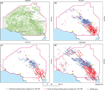
The process described above was applied to the GCAS TMI RTP data, resulting in an undivided regional lineament set (Fig 3a). The lineaments corresponding to the Gairdner Dolerite dykes were manually selected. This was done by picking the features that coincided with the magnetic anomalies associated with the highly magnetic Gairdner Dolerite. The selected lineaments are straight, broadly parallel and generally concentrated into a large dyke swarm that is up to 150 km wide and 750 km long (Fig 3). Individual lineaments are up to 85 km long, although generally less (i.e. between 4 and 72 km long).
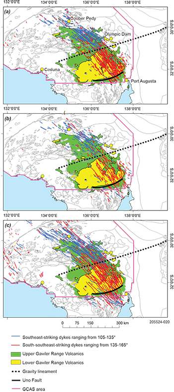
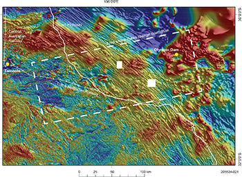
The automatically generated lineaments indicate a change in dyke trend across an east-northeast-trending zone in the central Gawler Craton (Fig 3b). This zone is located to the north of the main area of the upper Gawler Range Volcanics, in an area of outcropping lower Gawler Range Volcanics, and is herein referred to as the ‘bend’ (Fig 4). An examination of the dykes in the GCAS dataset indicate that most dykes define a change in orientation without being extended or offset (Fig 5). Some dykes continue across the bend for a short distance without changing orientation, leading to overlap of the 2 orientations.
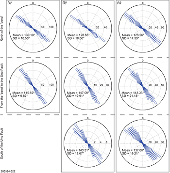
The lineaments corresponding to the dykes can be divided into 2 main populations: east-southeast-trending dykes with strikes generally <135°, and south-southeast-trending dykes with strikes generally >135°. The area south of the bend is dominated by south-southeast-striking dykes (86.3%; Figs 3b, 4a), with minor southeast-striking dykes (13.7%; Fig 3b). In the eastern and southern parts of the dyke swarm, several lineaments occur in a line suggesting they form straight segments of a single dyke. The area north of the bend mostly comprises southeast-striking dykes (69.8%; Figs 3b, 4a), with minor south-southeast-striking dykes (30.2%, Fig 3b). The difference in dyke orientation between these 2 areas can be seen on the rose diagrams (Fig 6a). In some cases, the south-southeast-striking lineaments line up, suggesting they are straight segments of a small number of these dykes. The south-southeast-trending lineaments appear to be evenly distributed across the main dyke swarm, with a spacing of ~20 km.
Figure 3 Line datasets described in this study. (a) All undivided lines generated from the GCAS TMI RTP dataset. (b) Lines generated from the GCAS TMI RTP dataset corresponding to the Gairdner Dolerite dykes. (c) Lines generated from the state TMI RTP dataset corresponding to the Gairdner Dolerite dykes. (d) Manually interpreted lines corresponding to the Gairdner Dolerite dykes.
Figure 4 Gairdner Dolerite dykes produced in different ways overlying the lineament and solid geology interpretation of the Gawler Craton. (a) Lines generated from the GCAS TMI RTP dataset corresponding to the Gairdner Dolerite dykes. (b) Lines generated from the state TMI RTP dataset corresponding to the Gairdner Dolerite dykes. (c) Manually interpreted lines corresponding to the Gairdner Dolerite dykes.
Statistical tests
The data was statistically analysed using an independent t-test to determine if the change in dyke orientation across the bend is significant. Initially, the lineaments from the GCAS dataset were divided into the lines north of the bend, and those to the south. The lines crossing the bend were not used in the statistical tests. The results of the statistical tests are shown in Table 2.
GCAS computer-generated lineaments
The statistical tests show that the lineaments generated from the GCAS TMI RTP that correspond to the Gairdner Dolerite dykes have a significant difference in orientation to the north and south of the bend (Figs 3b, 4a, 6a). The dykes to the north of the bend have a mean of 130.10° (standard deviation, SD = 10.58°), whereas the dykes to the south have a mean of 145.59° (SD = 9.82°). There is a mean difference of 15.49° (t = 26.668, df = 1235, p <0.0001; Table 2). This indicates that the change in orientation cannot be accounted for by normal variation within a single population, and they represent 2 distinct populations. The small standard deviations also suggest that the lineaments in the different zones have relatively uniform orientations (Table 2).
State TMI computer-generated lineaments
The GCAS dataset stops near the southern margin of the Gawler Range Volcanics, meaning the computer-generated lineaments do not continue despite the dykes continuing to the south. The southern boundary of the upper Gawler Range Volcanics corresponds to a prominent structure, the steeply north-dipping Uno Fault, which is interpreted as a growth fault that accommodated the accumulation of the thick volcanic sequence (Fig 4b; Turner 1975; Werner et al. 2019). To determine if there is a corresponding change in dyke orientation at the southern margin of the upper Gawler Range Volcanics, the computer-assisted lineament extraction process described above was applied to the statewide TMI RTP data. The lines produced were then subjected to statistical tests to see if there is a significant difference.
First, the lines generated from the state TMI RTP were divided into 2 populations corresponding to the dykes north of the bend, and those to the south (Fig 4). The dykes to the north of the bend have a mean of 128.86° (SD = 10.86°), whereas all the dykes to the south of the bend have a mean of 146.34° (SD = 11.35°). There is a mean difference of 17.48° (t = 15.960, df = 410, p <0.001; Table 2), which is significant, suggesting the orientations form 2 distinct populations. These populations can be seen on the rose diagrams (Fig 6b) and is like the pattern observed in the GCAS dataset (Fig 5a).
Second, the dykes south of the bend were divided into north and south of the Uno Fault (Fig 4). The independent t-test showed no significant difference in dyke orientation south of the bend between the lineaments intruding the upper Gawler Range Volcanics, and those south of the Uno Fault (Table 2). The dykes between the bend and the Uno Fault have a mean of 147.09° (SD = 10.91°), whereas the dykes to the south of the Uno Fault have a mean of 143.31° (SD = 12.67°). This is a mean difference of 3.78° (Table 2), which is not considered significant, suggesting the difference in orientation could occur within a single population of dykes.
Figure 5 GCAS TMI RTP data for the central to eastern Gawler Craton showing the curved dykes of the Gairdner Dolerite dyke swarm.
Table 2 Statistical means and standard deviations (SD) for the datasets
| Zone | GCAS TMI RTP (all lines; 2 areas) | State TMI RTP (all lines; 3 areas) | State TMI RTP (all lines; 2 areas) | Solid geology dyke lines (3 areas) |
| North | 130.10° (SD = 10.58°) | 128.86° (SD = 10.86°) | 128.86° (SD = 10.86°) | 128.26° (SD = 17.30°) |
| Central | 145.59° (SD = 9.82°) | 147.09° (SD = 10.91°) | 146.34° (SD = 11.35°) | 143.33° (SD = 21.15°) |
| South | 145.59° (SD = 9.82°) | 143.31° (SD = 12.67°) | 146.34° (SD = 11.35°) | 137.08° (SD = 19.21°) |
Solid geology Gairdner Dolerite dyke swarm
To assess the accuracy of the computer-generated lineaments, they were compared to the manually interpreted dykes that form part of the solid geology layer in the SARIG (‘All Map Layers’, ‘Gairdner Dolerite). The manually interpreted Gairdner Dolerite dyke swarm was divided into 3 populations that correspond to the same spatial groups as the state TMI RTP lineaments. These lines were subjected to the same statistical tests as the computer-generated lineaments, with the results summarised in Table 2, and shown as rose diagrams in Figure 6c.
The dykes north of the bend have a mean orientation of 128.26° (SD = 17.30°). This orientation is similar to the computer-generated lineaments in this area (Table 2). The dykes between the bend and the southern margin of the Gawler Range Volcanics have a mean of 143.33° (SD = 21.15°). There is a mean difference between these 2 populations of 15.06° (t = 11.305, df = 835, p <0.001), which is significant and similar to that observed for the computer-generated lineaments. The dykes to the south of the Gawler Range Volcanics have a mean of 137.08° (SD = 19.21°). There is a mean difference between the dykes between the bend and the southern margin of the Gawler Range Volcanics and those south of the Gawler Range Volcanics of 6.25° (t = 3.905, df = 876, p <0.001). This is significant and suggests the dykes change orientation at the southern margin of the Gawler Range Volcanics.
Summary of the statistical tests
The statistical tests indicate several features of the computer-generated lineaments related to the Gairdner Dolerite dyke swarm.
There are small differences between the means for the lines generated from the GCAS and state TMI RTP datasets in the different areas. This suggest the processing of the 2 aeromagnetic datasets produced similar results, which can be compared with confidence.
The standard deviations of the populations are generally small suggesting that the dykes in the different areas are relatively straight with uniform trends. The standard deviation of the lineaments generated from the state TMI to the south of the Uno Fault is ~2° greater than the other standard deviations, suggesting greater variation in line orientation in this area.
The results indicate a significant change in dyke orientation across an east-northeast-trending corridor to the north of the upper Gawler Range Volcanics (15.06–17.49° change in mean). This pattern is observed in both the lineaments generated from the GCAS and state TMI RTP datasets. The results from the state TMI RTP show there is less than 4° difference in mean orientation of the lines between the bend and the Uno Fault, and those to the south of the Uno Fault. This is not a statistically significant difference, indicating there is not a change in dyke trend at the southern margin of the Gawler Range Volcanics that would correspond to the change observed to the north at the bend.
The statistical tests indicate several features of the manually drawn lines of the Gairdner Dolerite dyke swarm. There is a change in mean orientation at the northern margin of the upper Gawler Range Volcanics of 15.06°. However, there is also a change of 6.25° in mean dyke orientation at the southern margin of the upper Gawler Range Volcanics. This difference is statistically significant and indicates the dykes form 3 populations with distinct orientations in the 3 areas. The standard deviations for the 3 areas are relatively high, ranging from 17.30–21.12°. This is consistent with the rose diagrams for the manually interpreted dykes, which show greater variation. The dykes south of the Uno Fault show a considerable range, effectively spanning the orientations in both areas north of the Uno Fault (Fig 6c).
Overall, it is possible to make some general observations about the different datasets:
- First, there is also a considerable difference in standard deviations between the computer-generated lineaments and manually drawn dykes, ranging from 9.82–12.67° for the former and 17.30–21.15° for the later. This suggests there is a greater degree of variation in orientation of the manually drawn dykes that is also seen in the rose diagrams (Fig 6c) but is not reproduced by the computer assisted lineament extraction. It is possible that the computer processing smooths and reduces variation in lineament orientation. Consequently, changing the values of the input parameters may produce lineaments that more closely match the manually interpreted dykes.
- Second, the lines from the 3 datasets have similar means and ranges to the 2 areas north of the Uno Fault (Fig 6; Table 2). All datasets show a statistically significant change in mean line and dyke orientation at the bend, and the changes in mean orientation are similar, ranging from ~15–17.5°. However, only the manually drawn dykes showed a statistically significant change in orientation at the Uno Fault. The change in mean orientation within the lines generated from the state TMI was not statistically significant, despite only being ~2° less than the change observed in the manually drawn dykes. However, there are differences to the south of the Uno Fault. To the south of the Uno Fault, the mean line orientations for the manually drawn dykes is up to ~6° different to the lines generated from the state TMI RTP in the same area. It is important to note that the state TMI RTP dataset south of the Uno Fault comprises a series of smaller aeromagnetic surveys of different scales. It is possible that the change in orientation of the dykes generated from the state TMI RTP may be an artifact of the different resolutions (i.e. line spacing) and vintages of the surveys stitched into the grid.
While it is only a minor difference, the existence, or non-existence, of a change in dyke orientation at the Uno Fault is important, as it may point to different possible geological processes and controls on dyke emplacement. The computer-generated lineaments point to a process where deflection of the dykes mainly occurred near the northern margin of the upper Gawler Range Volcanics. In contrast, the manually interpreted dykes point to a process where deflection occurred across both the northern and southern margins of the upper Gawler Range Volcanics. Whilst the manually interpreted dykes have only a small (but significant) mean difference to the computer-generated dykes to the south, the manually interpreted dykes also have a broader range in orientation (Fig 6c; Table 2). This supports the interpretation that the southern margin of the upper Gawler Ranges Volcanics (i.e. Uno Fault) influenced dyke emplacement. The implications of these different processes is discussed in the following section.
Implications for the Gairdner Dolerite dyke swarm and the Gawler Craton
The results of the statistical tests will be used to assess the processes that could have caused the change in orientation of the Gairdner Dolerite dyke swarm. Understanding these processes will help to determine the usefulness of the computer-generated lineaments corresponding to the dyke swarm.
It is possible to discount some potential processes for the change in dyke orientation. There is no evidence for the dykes being reoriented after their emplacement. Strike-slip or dip-slip shearing would have truncated and offset the dykes. Yet some dykes are observed to be curved with no evidence for overprint. Furthermore, shearing would also affect the rocks hosting the dykes, but there is no evidence for suitable deformation in the c. 1595–1575 Ma Gawler Range Volcanics and c. 1450 Ma Pandurra Formation. The distinct spatial distribution argues against 2 sets of temporally distinct dykes. Two sets of dykes in the same area typically form overlapping, intersecting sets, rather than the curved dykes seen in the Gawler Craton. This model would also require extension during each dyking event to be focused in separate areas, which would require decoupling between the 2 areas to allow differential extension and is considered unlikely.
This leads to the possibility that the change in dyke orientation is related to a change in competency or mechanical strength of the crust. This has been shown to cause deflection or refraction of structural elements, such as dilational fractures and shears. For example, experiments deforming samples with layers of different strengths under pure shear have shown that fracture orientation is controlled by the competency of the material (Douma et al. 2019). The fractures in the weak layers form as shear fractures, which are oriented at a moderate angle to the shortening direction. These fractures then propagate across the stronger layers as tensile fractures that are subparallel to the shortening direction. Consequently, it is possible that the change in dyke orientation may reflect a change in mechanical properties of the crust.
Computer-generated lineaments
The computer-generated lineaments derived from the GCAS and state datasets only have a statistically significant change in mean orientation near the northern margin of the upper Gawler Range Volcanics (i.e. the bend; Figs 4a, b). This suggests that the curvature is not solely related to the Gawler Range Volcanics, as there is not a corresponding change in orientation at the southern margin of the unit (i.e. Uno Fault). Instead, the observations indicate that there is an independent change in the crust near the northern margin of the upper Gawler Range Volcanics.
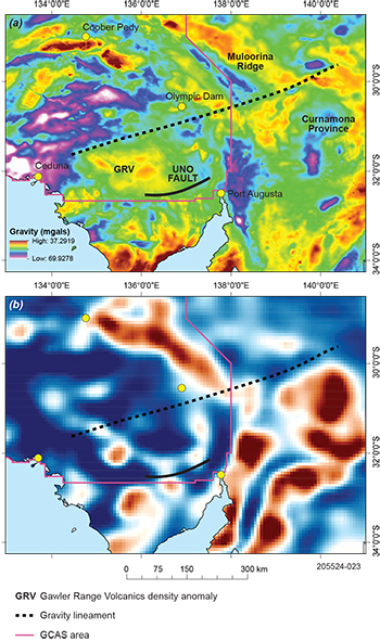
There is evidence for a change in lower crustal architecture in the geophysical data. The change in orientation of the dykes at the bend corresponds to an east-northeast-trending gravity feature that can be traced for almost 600 km (Fig 7a). To the southwest, the lineament can be traced along the gravity gradient associated with the main area of the Gawler Range Volcanics. The gravity high in this area has been attributed to a postulated thick, dense mafic underplate at the base of the crust that is related to the Gawler Range Volcanics (Blissett et al. 1993; Huynh et al. 2001). To the east-northeast, the lineament can be traced to the north of the Curnamona Province. In this area, the lineament is associated with truncation and the apparent sinistral offset and deflection of continuous, northwest-trending, broad wavelength gravity ridges, including the Muloorina Ridge (Fig 7a). This area is covered by Neoproterozoic to Phanerozoic rocks of the Adelaide Superbasin and Arrowie Basin (Jago et al. 2018; Lloyd et al. 2020; Preiss 2000). The gravity lineament is less obvious in the centre, beneath the central Adelaide Rift Complex, raising the question of whether it is a continuous feature masked by later Adelaidean rifting, or 2 separate gravity features that serendipitously line up.
The 3D AusLAMP magnetotelluric inverse models for the Gawler Craton provide evidence for a significant change in middle lower crustal grain in the vicinity of the bend (Fig 7b; Thiel et al. 2018). Conductors to the north of the bend are northwest-trending, whereas those to the south are north-northeast-trending. The 2 grains are truncated by the proposed east-northeast-trending structure. The southern end of the truncated conductor appears to be deflected by the structure with a sinistral sense of drag (Fig 7b). The magnetotelluric model shows the gravity lineament extending along the northern margin of the Curnamona Province as a break between conductors.
Consequently, it is possible that the bend corresponds to a major crustal boundary or structure. This would separate blocks with different crustal architecture, such as basement architecture, and geophysical properties.
Figure 7 (a) State gravity image of the Gawler Craton. (b) 30,716 m depth slice of the 3D AusLAMP magnetotelluric inverse model for the Gawler Craton.
Manually interpreted dykes
The manually interpreted dykes have a significant change in orientation near the bend in the north, and a less prominent, but still significant, change in orientation near the Uno Fault to the south (Fig 4c). This suggests that deflection of the dykes could be due to a change in crustal profile, and consequently mechanical strength of the crust, associated with the Gawler Ranges Volcanics. This change could be due to: (1) the distribution of the actual magma plumbing and emplacement system; (2) the thermal or metamorphic effect of the magmatic system on the host rock; or a combination of the 2. This process is consistent with the geophysical datasets. A prominent gravity high in this area is attributed to a postulated thick, dense mafic underplate at the base of the crust (Fig 7a), which is associated with the Gawler Range Volcanics (Blissett et al. 1993; Huynh et al. 2001).
There is a possibility that the dykes were affected by regional-scale structures related to the Gawler Range Volcanics – Hiltaba Suite. For example, the Uno Fault is a 200 km long structure, interpreted as a growth fault along the along the southern margin of the upper Gawler Ranges Volcanics, which controlled the distribution of volcanism and fluid flow (Turner 1975; Werner et al. 2019). It is possible that the northern margin of the upper Gawler Ranges Volcanics is similarly fault-bounded. These faults could separate crust of different strength, or different structural grains, leading to the refraction of the dykes.
It is possible that the east-northeast-trending structure and the Gawler Range Volcanics – Hiltaba Suite event may be related, and the different processes are connected. Little is known about the structural regime during emplacement of the Gawler Range Volcanics. Models for this period range from post-subduction delamination of lithospheric mantle (Skirrow et al. 2018), to plume interaction with a subduction zone (Betts et al. 2009), to progressive roll-back of a flat-lying subducting plate (Tiddy and Giles 2020). However, while these models considered the magmatic and mineral potential of the c. 1600–1570 Ma event, there was little consideration of the structural implications, leading to several questions. First, did a pre-existing structure influence the location of magmatic plumbing system associated with the Gawler Range Volcanics – Hiltaba Suite event? Second, did the onset of Gawler Range Volcanics – Hiltaba Suite magmatism and development of the dense underplate at the start of the event focus strain within the crust, leading to the development of the structure?
It is currently unclear what exactly caused the response in the geophysical datasets and the curving of the Gairdner Dolerite dykes. However, based on the greatest change in orientation of dykes at the bend, it is possible that there is a major boundary in the central and eastern Gawler Craton that separates crust with different mechanical properties. This difference may be due to differing basement grain or crustal profile. The reasons for this change may become obvious as work continues in the region.
Implications for controls on mineralisation
Understanding the control on the deflection of the dykes is important for understanding the crustal architecture with implications for mineral exploration in the central and eastern Gawler Craton. The possible east-northeast-trending major structure would run between Olympic Dam and Carrapateena, in the vicinity of Oak Dam. These deposits contain northeast-trending structures that are interpreted to have helped focus fluid flow (Hayward and Skirrow 2010). It is possible that these deposit-scale structures are second order features within a broader, mostly concealed east-northeast-trending corridor of deformation that would represent a crustal-scale channel for fluids (e.g. McCuaig and Hronsky 2014). Consequently, the feature revealed by this work may help to understand the controls on fluid flow and mineralisation in the Olympic Dam Cu–Au Province.
Implications for computer-generated lineaments
The workflow provides a potentially time- and cost-efficient tool for aiding the interpretation of basement geology and structures. This study has demonstrated that using automated linear feature extraction and analysis on large scale regional geophysical datasets can provide geologically meaningful insights. For example, this study was originally intended to examine the basement and determine whether computer-generated lineaments could be used to determine basement structures and domains with distinctive structural grains. It was expected that the Gairdner Dolerite dykes would obscure the basement trends. Yet plotting the lines using 30° bins with different colours (Figs 3, 4) serendipitously revealed the bend at the northern margin of the upper Gawler Range Volcanics. This led to a deeper examination of the dykes and why they change orientation, revealing a possible crustal-scale structure.
Why did the different datasets provide different statistical outcomes? It is possible that the computer-generated lineaments are too stylised, resulting in smooth, straight lines. This is supported by the standard deviations, where the populations of computer-generated lineaments have standard deviations of ~10°, suggesting relatively uniform populations. In contrast, the manually interpreted dykes have standard deviations of ~20°, which is much greater and indicates considerably more variability in dyke orientation. It may be possible to adjust the input parameters, particularly the angular difference threshold, to try and recreate lineaments distributions that are closer to the observed dykes.
Scale is also an important factor that will be based on the rationale of the geophysical survey. This study was an overview that used parameters that would produce a broad dataset, suitable for the regional scale. While not providing a definitive answer, the relatively uniform, smooth lineaments that were produced highlighted an area of complexity that warranted further investigation. Investigation could be through manual examination of the dykes (using the new GCAS data), or by changing the input parameters to create a more detailed lineament set that more closely approximated the natural system. A smaller scale survey would need different input parameters, with experimentation the best way to determine the best parameters for your requirements. A caveat is that the results of the processing represent only one data type and are indicative at best and will need to be compared with other datasets.
The work also highlights the benefit of using statistical tests to evaluate the relationships between populations of computer-generated and manually drawn lineaments. It allowed the degree of differences between populations to be objectively evaluated, leading to greater confidence in the conclusions. This process could become an integral part of future machine learning applications, and as inputs into prospectivity models.
Acknowledgements
We would like to thank Rian Dutch, Anthony Reid and Adrian Fabris (Geological Survey of South Australia, GSSA) for discussions on the geology of the eastern Gawler Craton and comments on early drafts of the manuscript. Kate Robertson (GSSA) produced the tif formats for the magnetotelluric slices from the original 3D inversions. Tom Wise (GSSA) and Clive Foss (CSIRO) are thanked for thorough, thoughtful reviews.
References
Douma LANR, Regelink JA, Bertotti G, Boersma QD and Barnhoorn A 2019. The mechanical contrast between layers controls fracture containment in layered rocks. Journal of Structural Geology 127:103856. doi:10.1016/j.jsg.2019.06.015.
Goode ADT 1970. The petrology and structure of the Kalka and Ewarara layered basic intrusions, Giles Complex, central Australia. PhD thesis, University of Adelaide.
Hayward N and Skirrow RG 2010. Geodynamic setting and controls on iron oxide Cu-Au (±U) ore in the Gawler Craton, South Australia. In Porter TM ed, Hydrothermal iron oxide copper-gold and related deposits: A global perspective, volume 3 - Advances in the understanding of IOCG deposits. PGC Publishing, Adelaide, pp 105–131.
Huynh T, Betts PG and Ailleres L 2001. Three-dimensional modelling of lithospheric-scale structures of South Australia. Journal of the Virtual Explorer 3:61–82.
Jago JB, Gehling JG, Betts MJ, Brock GA, Dalgarno CR, García-Bellido DC, Haslett PG, Jacquet SM, Kruse PD, Lansford NR, Mount TJ and Paterson JR 2018. The Cambrian System in the Arrowie Basin, Flinders Ranges, South Australia. Australian Journal of Earth Sciences 67(7):923–948. doi:10.1080/08120099.2018.1525431.
Lloyd JC, Blades ML, Counts JW, Collins AS, Amos KJ, Wade BP, Hall JW, Hore S, Ball AL, Shahin S and Drabsch M 2020. Neoproterozoic geochronology and provenance of the Adelaide Superbasin. Precambrian Research 350:105849. doi:10.1016/j.precamres.2020.105849.
McCuaig TC and Hronsky JMA 2014. The mineral system concept: the key to exploration targeting. In Kelley KD and Golden HC, Building exploration capability for the 21st century. Society of Economic Geologists, Inc, pp. 153–175. doi:10.5382/SP.18.
PCI Geomatics 2019. Geomatica user manual. PCI Geomatics, accessed 2020.
Preiss WV 2000. The Adelaide Geosyncline of South Australia and its significance in Neoproterozoic continental reconstruction. Precambrian Research 100(1–3):21–63. doi:10.1016/S0301-9268(99)00068-6
Tiddy CJ and Giles D 2020. Suprasubduction zone model for metal endowment at 1.60-1.57 Ga in eastern Australia. Ore Geology Reviews 122(103483). doi:10.1016/j.oregeorev.2020.103483.
Wingate MTD, Campbell IH, Compston W and Gibson GM 1998. Ion microprobe U–Pb ages for Neoproterozoic basaltic magmatism in south-central Australia and implications for the breakup of Rodinia. Precambrian Research 87(3–4):135–159. doi:10.1016/S0301-9268(97)00072-7.


