Ruth Murdie1, Tom Wise2, Mark Pawley2 and Rian Dutch2
1 Geological Survey of Western Australia, Department of Mines and Petroleum
2 Geological Survey of South Australia, Department of the Premier and Cabinet
Download this article as a PDF (5 MB); cite as MESA Journal 83, pages 11–19
Introduction
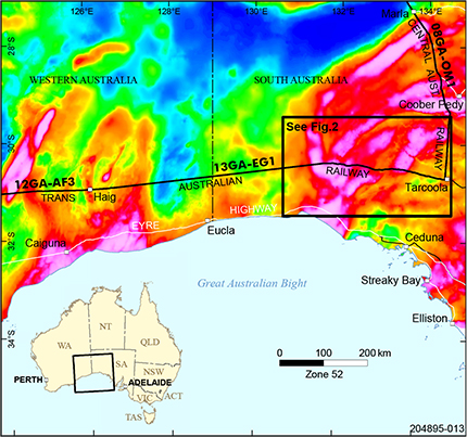
Figure 1 Location of the model box in relation to the seismic lines 13GA-EG1, 12GA-AF3 and 08GA-OM1 on a background image of the Bouguer gravity anomaly.
The recent acquisition and interpretation of the deep crustal seismic line 13GA-EG1 (Dutch, Pawley and Wise 2015) has allowed a new 3D model to be constructed for the western Gawler Craton. The new 3D model expands on the Eastern Gawler IOGC / Woomera Prohibited Area model (van der Wielen 2014), which sits to the north and east of this seismic line. As the Eastern Gawler IOCG / Woomera Prohibited Area model was created prior to interpretation of seismic line 13GA-EG1, some features conflicted with the more recent seismic interpretation. Two-dimensional forward modelling in the western Gawler Craton (e.g. Stewart and Betts 2010; van der Wielen et al. 2015) has revealed crustal-scale structures that can be represented well with geophysical modelling techniques, and we aim to provide greater 3D constraint in the form of a crustal architecture model.
The new model runs from the approximate western boundary of the western Gawler Craton at the Jindarnga Shear Zone eastwards to the start of the north–south 08GA-OM1 seismic line at Tarcoola (Fig. 1). In the north–south dimension the model runs ~100 km to the north and south of 13GA-EG1.
This article will present some of the constraints which were used to construct a geological framework. Modelling methodologies and some of the geophysical constraints used to develop the 3D model will be detailed and some of the results will be presented and discussed.
Geological setting
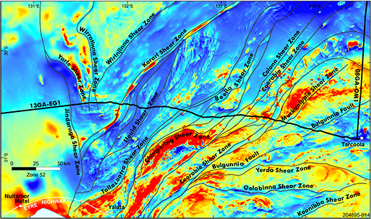
Figure 2 Surface traces and names of the faults shown on the background of the TMI image from which they were originally derived.
The model encompasses an area of the western Gawler Craton from where it dips westwards under the Eucla Basin in the west, across to the central Gawler Craton in the east. Most of this area is poorly exposed. Geophysical images and drillhole intersections show that it is a structurally and lithologically complex area. The area is divided into geological domains based on geophysical characteristics (Fig. 2) which are explored in this study. The basement domains of the western Gawler are Neoarchean to Paleoproterozoic and have been affected by orogenic and magmatic events within the Proterozoic. Domains featured in this model include the Nawa, Christie, Fowler, Nuyts, Wilgena and Harris domains and Coober Pedy Ridge.
The basement domains are overlain by various basins from the Neoproterozoic onwards; these include the Neoproterozoic to Devonian Officer Basin, the intracratonic Permo-Carboniferous Arckaringa Basin, the Bight Basin which is a Cretaceous rift basin, and intracratonic Cenozoic Eucla Basin.
The basement rocks have mineral potential, for example, gold in the Neoarchean rocks (Poustie, Bamford and Daly 2002), nickel and copper sulfides in the mafic and ultramafic rocks, and magnetite iron ore in gneisses and banded iron formations (e.g. the Gawler Iron Project of Iron Road Limited). The basins also have potential for gas and oil (Morton and Drexel 1997), mineral sands (Hou et al. 2011) and paleochannel-hosted uranium (Hou and Alley 2003). Understanding the geological structure and processes which have affected this region will increase our understanding of the origin and location of these diverse resources.
Model components
Basins
Much of the western Gawler Craton is obscured by sedimentary cover which has been included in this model in a simplistic manner. All the basins are relatively thin compared to the total crustal thickness in the area of the model and have been assigned an average depth, estimated from seismic sections or representative drill cores. Individual surfaces are given for all the basins. However, for modelling of the gravity field, the surfaces of the Officer, Arckaringa and Bight basins were combined together as one ‘basins’ volume. The Eucla Basin was not included as it is too thin. This basins volume forms a veneer across much of the Nawa and Coompana domains and a small strip across the north of the model linking to the basin interpretation on the 08GA-OM1 seismic line. Outlines of the basins are taken from the South Australian Resources Information Gateway (SARIG) solid geology layer. We do not intend the basins volume to be an accurate representation of the true cover thickness, rather it is an estimate for the purposes of this crustal-scale model.
Domains and seismic provinces
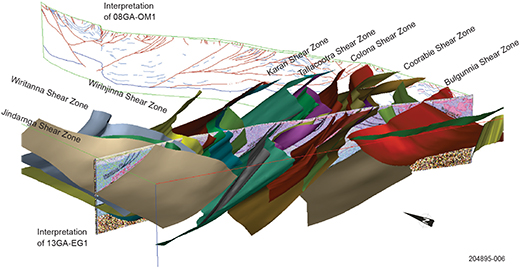
Figure 3 Selected faults from the model superimposed on the interpretations of the seismic lines 13GA-EG1 and 08GA-OM.
The model is based on the discrete fault-bounded blocks that make up the crust of the western Gawler Craton. The surface traces of faults (Fig. 2) have been taken from Reid and Dutch (2015). These faults divide the western Gawler Craton into geological domains and are described more fully in the same publication and also in Ferris, Schwarz and Heithersay (2002) and Fraser and Reid (2007). Profiles of faults are taken from the interpretation of the seismic line 13GA-EG1 (Doublier et al. 2015) and from the interpretation of the 08GA-OM1 line (Korsch et al. 2010; Fig. 3). Where the two lines meet, preference was given to the 13GA-EG1 line as the resolution and definition was greater, although a compromise was sought where possible where conflicting interpretations occurred.
Major domain-bounding faults are imaged as well as prominent faults internal to domains. This was done to see if there were any internal differences within the domains. Many major structures are actually composed of several strands and this model tries to capture this by including several surfaces to represent one fault.
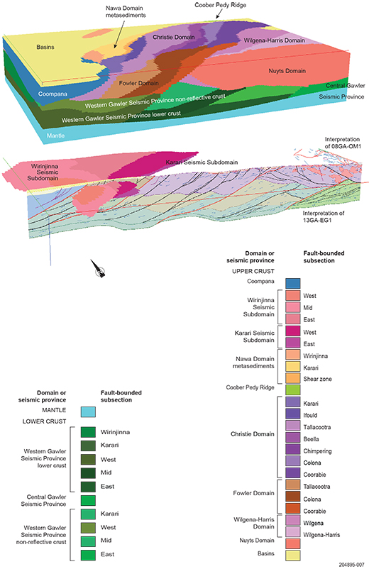
Figure 4 Block model of the western Gawler Craton showing the volumes between faults filled by geological domains. The lower block shows the detail of the Wirinjinna and Karari seismic subdomains with the basins and all other domains and seismic provinces stripped away. A colour key to the individual blocks is given. Each block is named initially by the domain and then by the footwall bounding fault.
After constructing the fault framework, the 3D rock volumes between faults were filled with pixels. These pixels were assigned properties that correspond to the various geological domains found in the Coompana Province and Gawler Craton (Fig. 4). Descriptions of each component interpreted from seismic line 13GA-EG1 can be found in Doublier et al. (2015), whilst Reid and Dutch (2015) and references therein, and especially Ferris, Schwarz and Heithersay (2002), provide details on the geology.
Upper crustal blocks are referred to as domains, as there are geological constraints from sparse boreholes and exposure. Most of the upper crustal blocks extend to ~20 km deep. However, beneath the Nawa Domain, the upper crust is further subdivided into two seismic subdomains. These have not been sampled by drilling but identified on the basis of the seismic section.
In contrast, middle and lower crustal units that are not exposed and are only defined by their reflective character in the seismic sections are termed ‘seismic provinces’ (e.g. Korsch et al. 2010).
Away from the seismic lines, spatial distribution and vertical thickness of seismic provinces have been extrapolated following the trends seen in the seismic line and the near-surface geophysical expression of major structures. It is therefore possible that their strikes are different from that depicted, due to lack of constraints off-line. This was investigated in the inversion of gravity data.
The crust of the western Gawler Craton can be divided into two parts, which are separated by the Karari Shear Zone. The crust to the east of this shear is composed of two layers: upper crustal domains, and variably reflective lower crustal layers. The large-scale structures that separate and dissect domains can often be traced into the underlying crust with some structures interpreted to offset the Moho. The crust to the west of the Karari Shear Zone consists of three layers: fault-bound upper domains (e.g. Nawa Domain); a middle crust (e.g. Wirinjinna and Karari seismic subdomains) and a lower crust. Surfaces that define the base of the upper crust and the base of the non-reflective middle crust have been included in the model as generic surfaces where variably reflective regions are not obviously fault-bound.
Upper crustal regions include the Coompana Province (which has not been subdivided in this model), the Nawa Domain which overlies the Wirinjinna and Karari seismic subdomains, the Christie Domain, the Fowler Domain (which is not imaged in seismic line 13GA-EG1), the Nuyts Domain, and the Wilgena and Harris domains which have been combined as a single entity south of the Bulgunnia Shear Zone in the model. A small fraction of the Coober Pedy Ridge is present in the northeastern extremity of the model.
Lower crustal domains include a non-reflective crust, the variably reflective Western Gawler Seismic Province, and the highly reflective lower crust of the Central Gawler Seismic Province at the eastern end of 13GA-EG1.
The reflective lower crust of the Western Gawler Seismic Province was hypothesised to be a single layer between the Bulga and Jindarnga shear zones, with locally variable reflectors suggesting a structural grain which may or may not represent thrust ramps (Doublier et al. 2015). This reflective lower crustal unit was modelled as discrete blocks to see if there were differences in density between regions. As densities were similar (within error), we can confirm the reflective lower crustal unit comprising part of the Western Gawler Seismic Province is likely to be a continuous layer, dissected by major structures, and not juxtaposed blocks of different densities.
The majority of the Moho surface came from the interpretation of the eastern end of the 13GA-EG1 (Doublier et al. 2015). This showed a deep Moho with a base level of 45 km with two deeper areas of down to 54 km beneath the boundaries between the Nawa and Christie domains, and the Christie and Wilgena domains. The eastern extremity of the Moho in the model was also constrained by the southern end of seismic line 08GA-OM1. At the junction of the two seismic lines, the Moho was correlated at 43.5 km. Away from the seismic line, interpolated data from the Australian Seismological Reference Model (AuSREM; Kennett and Salmon 2012) was added to the seismic line constraints.
Gravity and total magnetic intensity modelling methods
The aim of the gravity modelling was three-fold: (i) to see if there were significant density variations between the blocks which may indicate differing origins; (ii) to broadly show density variations within the crust; and (iii) to better define geological unit geometries away from the seismic lines. All inversion modelling was done using VPmg inversion software by Fullagar from within GOCAD.
The geometry of the surfaces and volumes are most confidently defined along the seismic lines. Elsewhere, the geometry is loosely constrained by the AuSREM model. A regional solid model of blocks 3 x 3 x 0.25 km was built and each region assigned to a geological domain as described above and given a representative density.
The gravity data which was originally gridded at 400 m cell size, was resampled to 3 km and upwardly continued to 20 km. This was done to investigate the long wavelength, deeper features. Initial densities were set to either those densities finalised on by van der Wielen et al. (2015) or estimated from the adjacent block if there was no value given (values used are given in a metadata document contained in the model release). The initial model used a relatively uniform density across similar crustal levels to avoid bias. Initially, forward models were run and manual adjustments made to get a good starting model for inversions. The first inversion was a homogeneous property model inversion which allows the bulk density of each block to vary in order to get a basic framework of densities. Then a geometry inversion was done to adjust the shape of each geological unit to better fit the observed data. Then the homogeneous inversion was repeated. The final step, using the upward continued gravity, was to do a heterogeneous inversion. This allows the inversion to vary the density within each body to fit anomalies that have wavelengths within the length of a geological unit. The last inversion compared the model to the Bouguer anomaly at ground level and allowed the density within each block to vary heterogeneously to define the higher resolution, shorter wavelength features.
The magnetic variations of each block were investigated using inversions of the total magnetic intensity (TMI) data. A first pass heterogeneous property inversion of the TMI data for susceptibility differences across the upper crustal regions was completed also using the VPmg software. This heterogeneous inversion allowed the software to assign susceptibility values to pixels across each block in order to approach a match to the observed TMI. This was also done on a 3 km cell size. Hence it is very coarse compared to the observed data (originally gridded at 80 m cell size) and was used to look at the variations in magnetic signature in each block rather than to define structures internal to the blocks.
3D inversion results
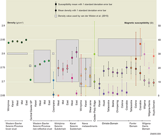
Figure 5 Graphs of density and susceptibility of density and susceptibility variations between each block, and also by domain. Values used by van der Wielen et al. (2015) are given as grey blocks behind the point data.
The major outcome of the inversion procedure was to show that by using geologically representative densities for each block, there was little variation in the final structural model from the original interpretation of the seismic line. Furthermore, it also adds confidence in the interpretation of the structures between the two seismic lines. It should be noted that although the constraints of the seismic interpretation were used in the construction of this model, many assumptions were also necessary, such as assuming consistent geometries between seismic lines. Whilst this density model is one of an infinite number of possibilities which could fit the observed gravity data, it does however confirm that this 3D interpretation is a plausible one.
The geometry inversions that were run changed depths to boundaries and hence shape of blocks, to better match the calculated model gravity response to the observed gravity anomaly. These inversions did not use any fixing points to constrain the movement of boundaries. Therefore the new geometry was allowed to diverge from the original interpretation of the seismic line. Despite this freedom, the modelling only resulted in small differences in the interpretation. These include a slight difference in the mid-crustal geometry of the Jindarnga Shear Zone, and a slight difference in the depth of the boundary between the Christie Domain and underlying Western Gawler Seismic Province.
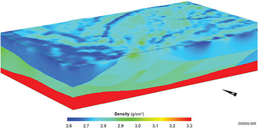
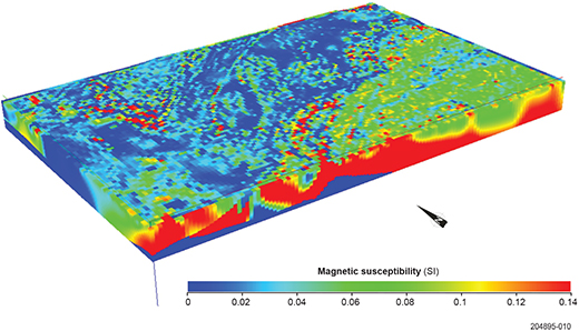
Comparisons of the densities and susceptibility variations of each block across each domain and to neighbouring domains are shown graphically in Figure 5 and block models of the density and magnetic structure are shown in Figures 6a and b.
There was much greater variation in the magnetic properties with large standard deviations within each segment than with the densities (Fig. 5). This is to be expected from the areas of highly variable and, in places, very strong TMI signal. The model showed the differing origins of the domains based on the susceptibility ranges seen in each block.
Figure 6 (a) Block model of the western Gawler Craton showing the density variations across the whole model as a result of the inversions of the Bouguer anomaly. Boundaries between the blocks are visible, particularly in the lower crust due to each block being inverted independently of its neighbouring blocks.
Discussion
Major features that became apparent as a result of the inversions include:
- The different lower crustal blocks of the Western Gawler Seismic Province all had very similar densities implying similar material as opposed to juxtaposed blocks of different origins. The whole of the western Gawler Craton appears to be floored by a consistent and continuous layer.
- One of the lower crustal inclined reflective layers that appears to rise and form ramps in the interpretation of 13GA-EG1 is interpreted to pinch out against the Coorabie Shear Zone to the north of the model. This may suggest that the ramp structures in the mid-lower crust pre-date major movement along the Coorabie Shear Zone.
- The Wirinjinna and Karari seismic subdomains appear to have very different densities with the Karari having a relatively high density, higher than that of the non-reflective middle crust of the Western Gawler Seismic Province. The Wirinjinna Seismic Subdomain had densities similar to the Christie and Fowler domains. One possible explanation is that the Karari Seismic Subdomain may have been exhumed from deeper than crustal blocks either side as it shows higher densities and is known to contain high-grade metamorphic rocks, e.g. Moondrah Gneiss (Teasdale 1997; Dutch and Hand 2009). Constraints on metamorphic grade in the Wirinjinna Seismic Subdomain are limited.
- The Christie Domain was split into segments defined by the major crustal structures. There are noticeable variations across the domain. The Karari fault-bound subsection of the Christie Domain (Fig. 4) is noticeably less dense than surrounding fault-bound subsections (e.g. Ifould, Tallacootra). Although the host rock in this subsection is the Mulgathing Complex of the Christie Domain, this area is extensively intruded by granites, likely of the Tunkillia Suite which are apparent in the TMI image. These volumetrically large plutonic bodies contribute to the lower density and the higher susceptibility of this block of the Christie Domain compared to all other Christie blocks to the northeast (Fig. 5). Apart from this, all the Christie and Fowler domain segments have densities within the standard deviation of each other. However, this value is somewhat lower than the value van der Wielen used in his model and measured for the Mulgathing Complex which comprises much of the two domains. The difference in model density values may be attributable to the higher densities used in this model in the lower crust compared to the model of van der Wielen et al. (2015), hence not requiring such high densities in the upper crust. The values used in this study reflect the bulk value in a modelled block and may include a lower density component.
- Differences in the Christie and Fowler domains are seen in the magnetic signatures. Whereas the Christie Domain has very low susceptibilities, the Fowler Domain has much more high susceptibility material in it. This may reflect the presence of variably magnetic Hiltaba Suite 1590 Ma magmatism that occurs in the Fowler Domain but not the Christie Domain (Reid and Dutch 2015).
- The Coompana Domain had a significantly lower density than all the other units, having a similar density to the crustal average, indicating a higher proportion of felsic rocks (e.g. Spaggiari and Smithies 2015; Wise, Pawley and Dutch 2015) than the volcanic and metamorphic rocks of the Gawler Craton.
Conclusion, further work and links
This model builds on the interpretation of the 13GA-EG1 and 08GA-OM1 seismic lines and attempts to visualise the geology in-between. Inversions generally support the interpretation of 13GA-EG1, although there were some conflicts with the interpretation of 08GA-OM1. The inversions give more defining features to the individual components of the region.
Differences in physical properties clearly show the difference in lithologies and metamorphic/intrusive histories of upper crustal domains overlying the Western Gawler Seismic Province compared to either of those overlying the Central Gawler Seismic Province or the Coompana Province. However, similarities between blocks within each domain support the current domain definitions. Only in the Wirinjinna and Karari seismic subdomains do internal differences still leave unanswered questions and reflect the sparsity of geological constraint within these regions.
This model is the first of three models which will cover the length of the seismic line 13GA-EG1; the others being the Albany–Fraser Orogen model in Western Australia and the Coompana model which straddles the Western Australia – South Australia border. These are being worked on and will be published in the coming years to produce a continuous crustal architecture and density model between the Gawler and Yilgarn cratons.
The model can be downloaded from the SARIG catalogue as a GOCAD project and a 3D.pdf. A full metadata package is included, including constraints used and more detail on processing methodologies.
Acknowledgements
George Gouthas (Geological Survey of South Australia, GSSA) is thanked for invaluable assistance in the delivery of the 3D model. Staff from the GSSA, Geological Survey of Western Australia and Geoscience Australia involved in initial seismic interpretations contributed greatly to furthering the geoscience knowledge of this region, which we have drawn on to create this model.
References
Ferris GM, Schwarz MP and Heithersay P 2002. The geological framework, distribution and controls of Fe-oxide and related alteration, and Cu-Au mineralisation in the Gawler Craton, South Australia, Part I: geological and tectonic framework. In TM Porter ed., Hydrothermal iron oxide copper-gold and related deposits: a global perspective, Vol. 2. Adelaide, PGC Publishing, pp. 9–31.
Fraser GL and Reid AJ 2007. Time-space evolution of the Gawler Craton. In NL Neumann and GL Fraser eds, Geochronological synthesis and time-space plots for Proterozoic Australia, Record 2007/06. Geoscience Australia, Canberra, pp. 3–33.
Hou B, Keeling J, Reid AJ, Warland I, Belousova E, Frakes L, Hocking R and Fairclough M 2011. Heavy mineral sands in the Eucla Basin, southern Australia: deposition and province-scale prospectivity. Economic Geology 106:687–712.
Kennett BLN and Salmon M 2012. AuSREM: Australian seismological reference model. Australian Journal of Earth Sciences 59:1,091–1,103.
Korsch RJ, Blewett RS, Giles D, Reid AJ, Neumann N, Fraser GL, Holzshuh J, Costelloe RD, Roy IG, Kennett BLN, Cowley WM, Baines G, Carr LK, Duan J, Milligan PR, Armit R, Betts PG, Preiss WV and Bendall BR 2010. Geological interpretation of the deep seismic reflection and magnetotelluric line 08GA-OM1: Gawler Craton-Officer Basin-Musgrave Province-Amadeus Basin (GOMA), South Australia and Northern Territory. In RJ Korsch and N Kositcin eds, GOMA (Gawler Craton-Officer Basin Musgrave Province-Amadeus Basin) Seismic and MT Workshop 2010, Record 2010/39. Geoscience Australia, Canberra, pp. 63–86.
Spaggiari CV and Smithies RH eds 2015. Eucla Basement Stratigraphic Drilling Results Release Workshop: Extended Abstracts, Record 2015/10. Geological Survey of Western Australia, Perth.
Stewart JR and Betts PG 2010. Implications for Proterozoic plate margin evolution from geophysical analysis and crustal-scale modelling with the western Gawler Craton, Australia. Tectonophysics 483:151–177.
Teasdale J 1997. Methods for understanding poorly exposed terranes: the interpretive geology and tectonothermal evolution of the western Gawler Craton. PhD thesis, University of Adelaide.


